Probing stock using the work probe
Hazards


Instructions
To successfully set a work offset you must define the origin in three different axes: X, Y, and Z. A large number of the pre-made probing templates will set all three in one go, but you also have the option to use several templates in sequence to set different axes seperately.
In this example we will set all three to the top centre of the stock using the “Rectangle Block” template.
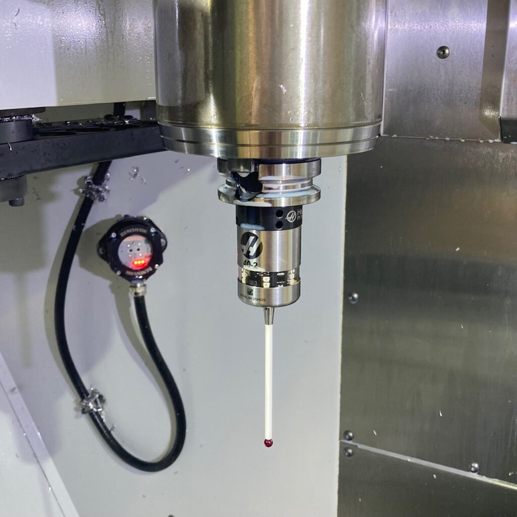
Change to the tool loaded into the spindle to the work probe.
Select MDI mode.
Type T199 then press ATC FWD or ATC REV.
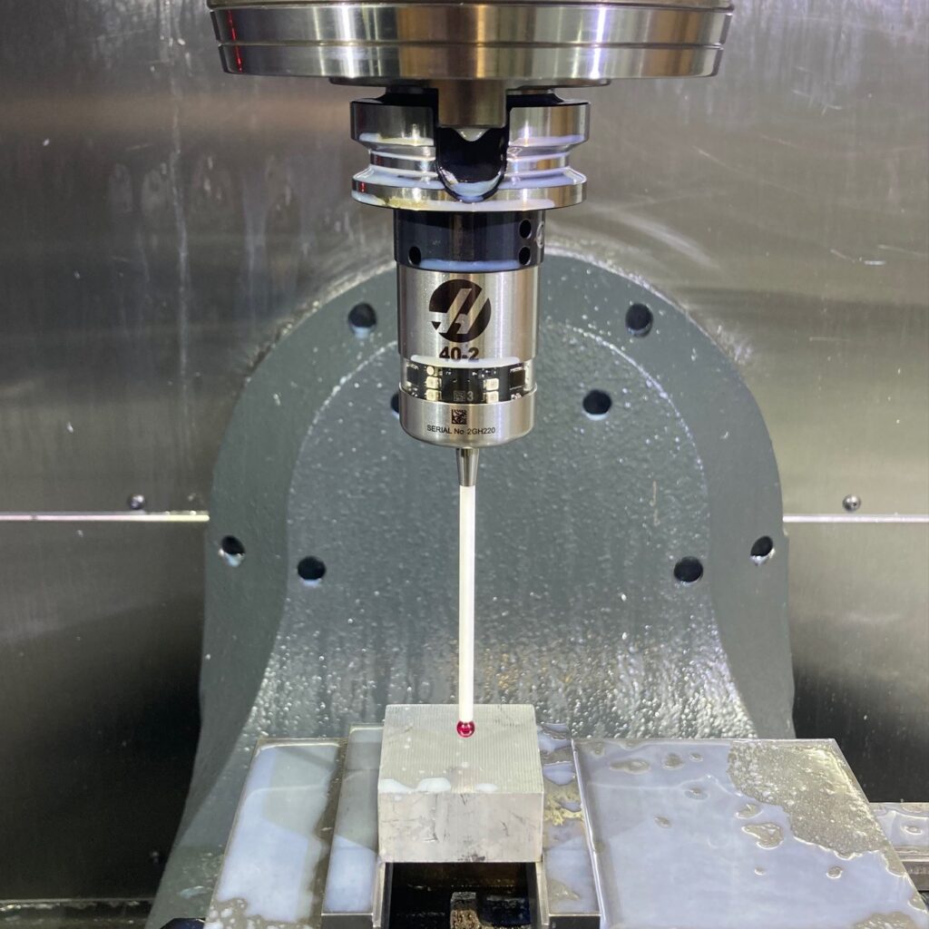
Using Handle Jog mode position the tip of the probe over the top centre of your stock, between 5-10 mm away from the top surface of the material.
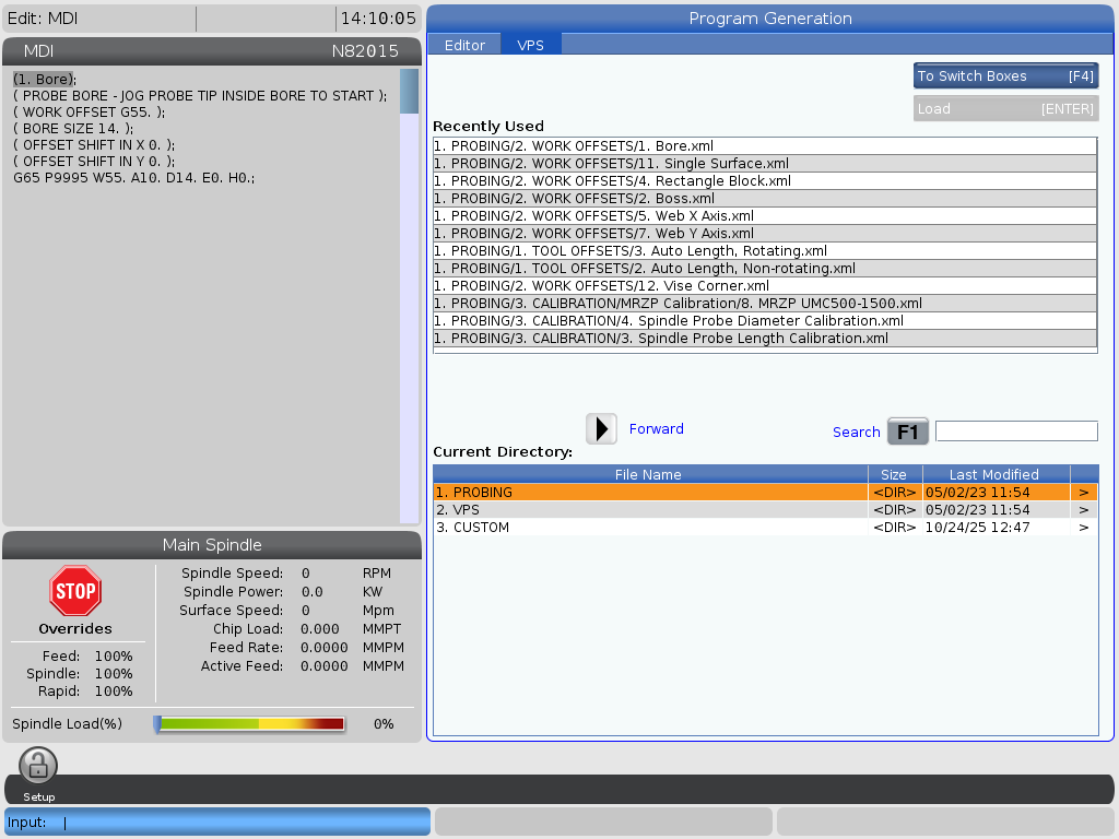
Select Edit mode, and press Edit again to get to the tabs at the top of the screen.
Cursor Right across to VPS, then Cursor Down into the VPS window to highlight “Probing”. Cursor Right to enter the probing screen.
If you have been probing tools you may end up in a tool probing window. Cursor Left until you reach this screen.
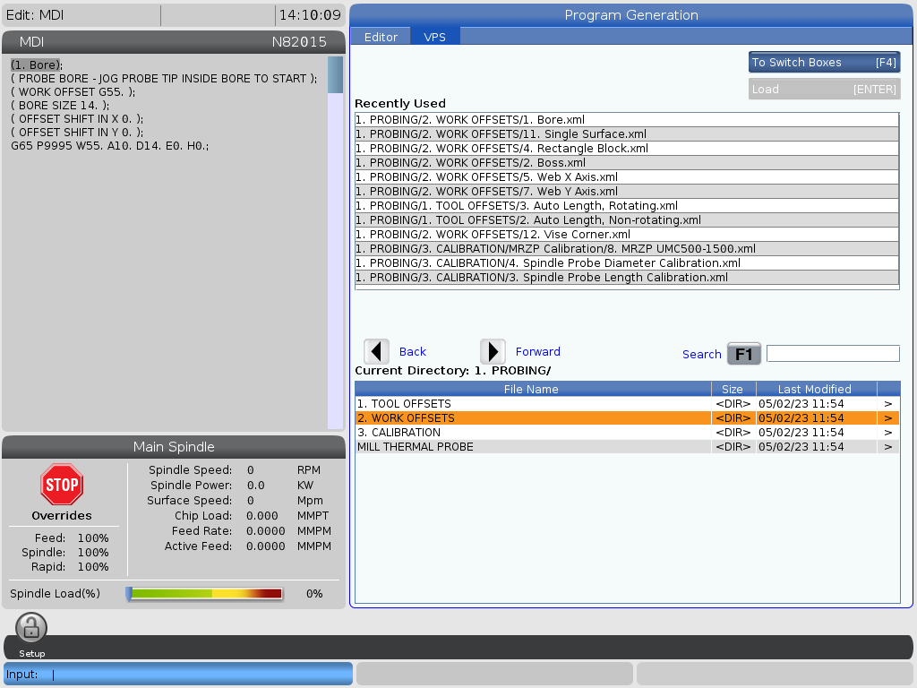
Select Work Offsets and Cursor Right to enter the page.
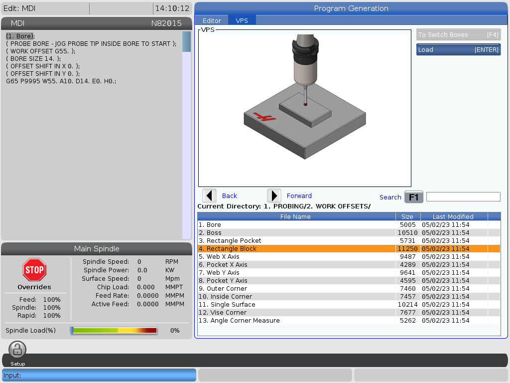
From the list of Work Offset Probing templates select “Rectangle Block” and then Cursor Right to enter the page.
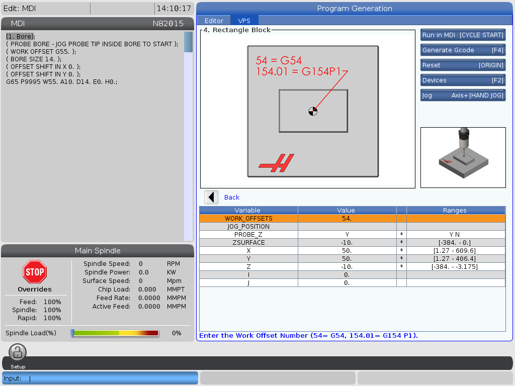
Complete the questions from top to bottom, using Cursor Down to move between the rows.
Select the work offset you wish to use by typing the number and pressing Enter.
For example, to set the G54 work offset, type “54” and press Enter.
Cursor Down past the “JOG_POSITION” line to “PROBE_Z”
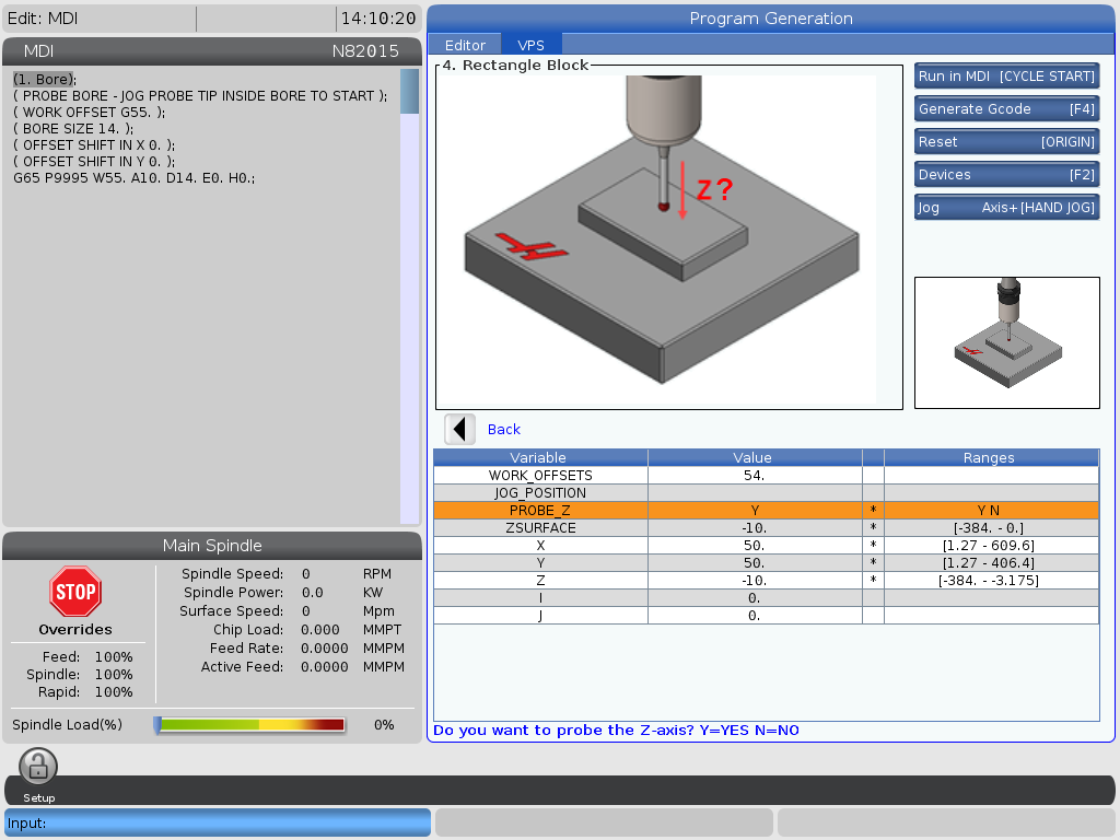
The “PROBE_Z” line is asking if you wish to probe the top surface of the material as the Z plane. In this case, we do, as we are setting the top centre of the block as our origin.
Type “Y” and press Enter, then Cursor Down.
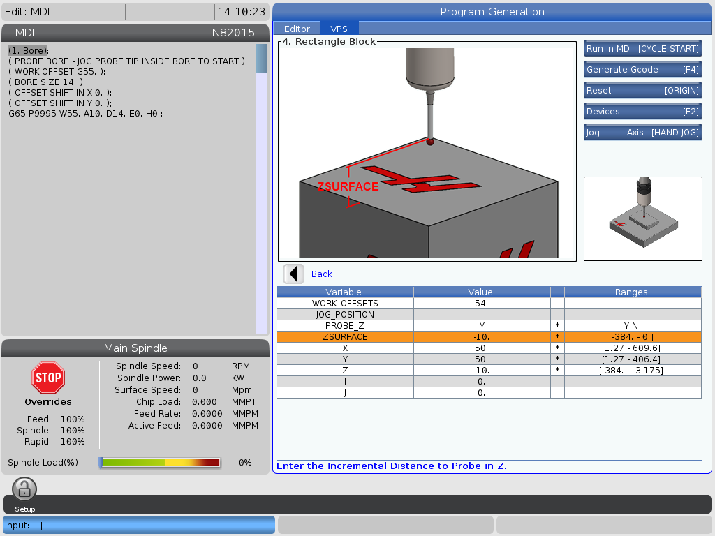
“ZSURFACE” defines how far below the current position the probe should look for the surface to probe.
In this case the value is “-10”, which means the surface should be 10mm or less below the tip of the probe. You can adjust this setting as needed, but beware of using overly large ZSURFACE values as you may accidentally crash the probe.
Cursor Down to the “X” line.
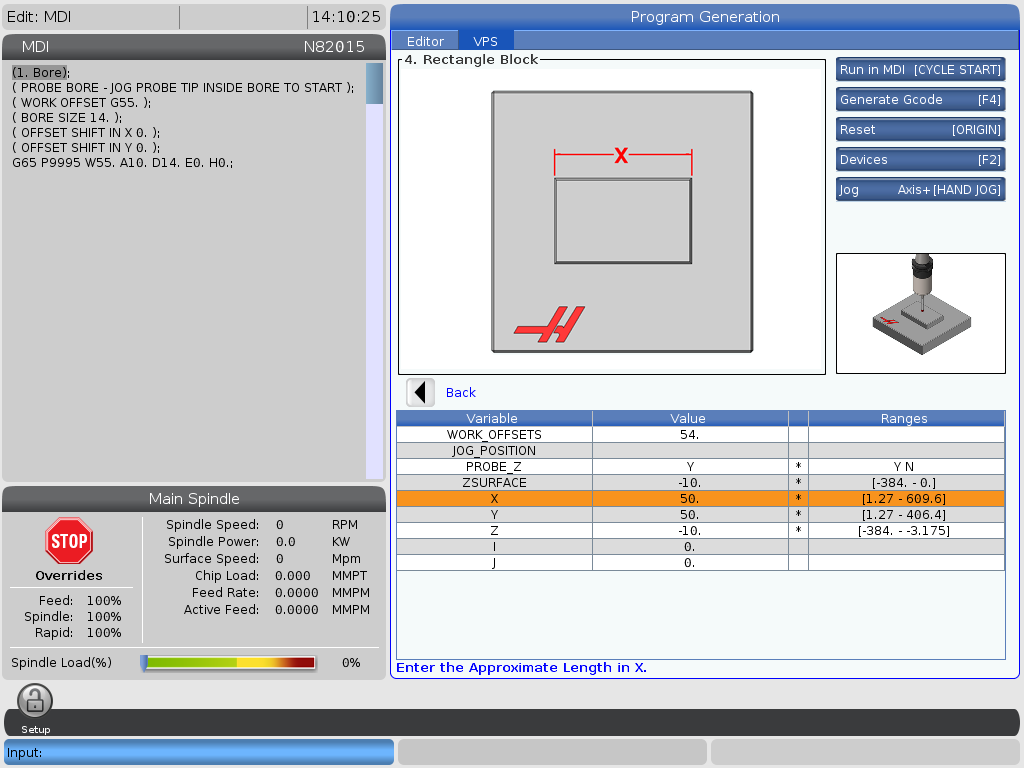
Type the size of your stock in the X axis (left to right) including the decimal point, and press Enter.
Note that this is the size of the feature you are measuring, so if your stock is 75mm wide you should type “75.” Rounding up to the nearest millimeter is fine.
Cursor Down to the “Y” line.
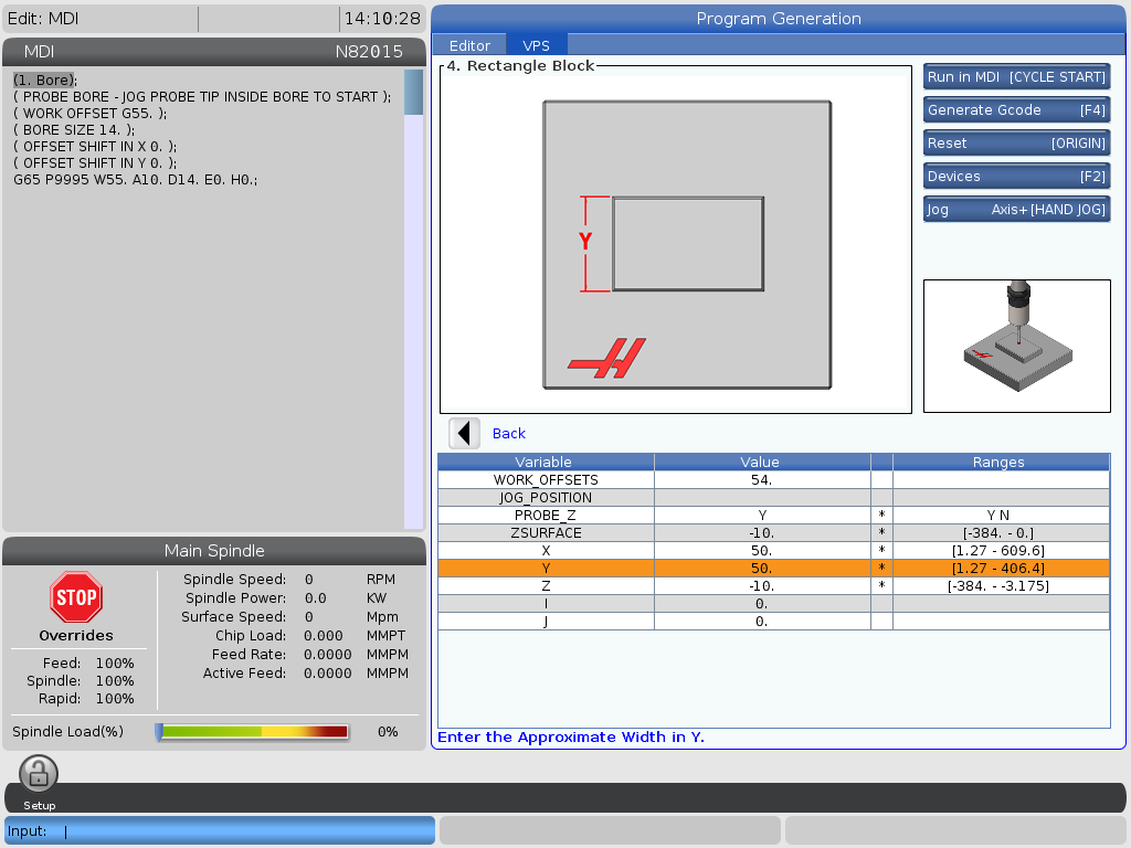
Type the size of your stock in the Y axis (front to back) including the decimal point, and press Enter.
Again, this is the size of the feature you are measuring, so if your stock is 48mm you should type “48.”
Cursor Down to the “Z” line.
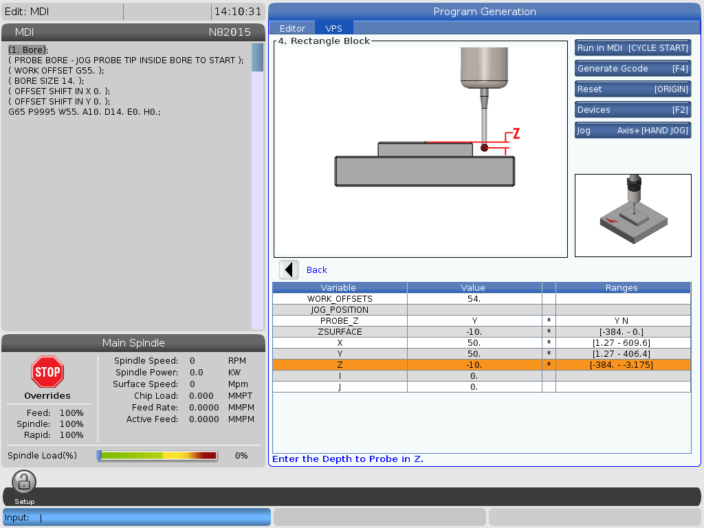
The “Z” setting determines how far down the probe should move down the material before it tries to probe the sides.
If you answered “Yes” to PROBE_Z, this will be the distance from the probed top surface of the material to the tip of the probe, if you answered “No” this will be how far the probe moves down from its current position.
You do not need to fill in any values for I and J, leave these as zero.
Press F4 to generate the G-code, and press 2 to output the code to the MDI window.
The generated G-code will appear in the MDI window to the left. Read through it to check that everything is correct.
Once you’re happy, press Cycle Start to run the probing routine.
Once the probe routine has finished the X, Y, and Z positions are set for your selected work offset. You can check what values have been set by looking in the work offsets table in the Offsets display.